For order or more information about our products please contact us
Description
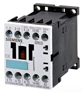
Siemens 3RT IEC Contactor Size S00, 20 AMP with 1 N.C. base mounted auxiliary contact and a 110v50Hz/120v60Hz coil.
AC AND DC OPERATION
IEC 60 947, EN 60 947 (VDE 0660), UL 508
DESIGN
The 3RT1 contactors are suitable for use in any climate. They are safe from touch to DIN VDE 0106 Part 100. The 3RT1 contactors are available with screw connections or with Cage Clamp connections. An auxiliary contact is integrated in the basic unit of size S00 contactors. The basic units of sizes S0 to S3 only contain the main conducting paths. All the basic units can be extended with auxiliary switch blocks. Cabinet units with 2 NO + 2 NC (terminal designations acc. to EN 50 012) are available as of size S0; the auxiliary switch block is removable. The size S3 contactors have removable box terminals for the main conductor connections. Ring cable lugs or bars can thus also be connected.
CONTACT RELIABILITY
If voltages ≤ 110 V and currents ≤ 100 mA are to be switched, the auxiliary contacts of 3RT1 contactors and 3RH11 contactor relays should be used to ensure good contact stability. These auxiliary contacts are suitable for electronic circuits with currents ≥ 1 mA at a voltage of 17 V. For the short-circuit protection of contactors without an overload relay, see the technical data.
SHORT CIRCUIT PROTECTION OF CONTACTORS
For the short-circuit protection of contactors with an overload relay, see section 3.
MOTOR PROTECTION
3RU11 overload relays can be mounted onto the 3RT1 contactors for protection against overloads. The overload relays must be ordered separately (see section 3).
SURGE SUPPRESSION
The 3RT1 contactors can be retrofitted with RC elements, varistors, diodes or diode assemblies (combination of an interference suppression diode and a Zener diode for short tripping times) for suppressing opening surges in the coil. The surge suppressors are plugged onto the front of size S00 contactors. Space is provided for them next to a snapon auxiliary switch block. With all size S0 to S3 contactors, varistors and RC elements can be plugged on directly at the coil terminals, either on the top or underneath. Diode assemblies are available in two different designs with different polarities. Depending on the application, they can be attached either only on the bottom (assembly with circuitbreaker) or only on the top (assembly with overload relay). The plug-in direction of the diodes and diode assemblies is determined by a coding device. Exceptions: 3RT19 26-1T.00 and 3RT19 36-1T.00; in these cases the plug-in direction is identified by “+” and “–”. Coupling relays are supplied either without surge suppression or with a varistor or diode connected as standard, according to the design.
Note
The opening times of the NO contacts and the closing times of the NC contacts increase if the contactor coils are protected against voltage peaks (interference suppression diode 6 to 10 times; diode assemblies 2 to 6 times; varistor +2 ms to 5 ms).
| Horsepower Ratings | Auxiliary Contacts |
Screw Connection | |||||||
| AC-3 Maximum Inductive Current |
Horsepower ratings of three-phase motors |
AC-1 Maximum Resistive Current |
|||||||
| AC3 | UL | 200V HP |
230v HP |
460v HP |
575v HP |
Amps | N.O. | N.C. | |
| Size S00 | |||||||||
| 12 | 20 | 3 | 3 | 7.5 | 10 | 22 | – | 1 | 3RT1017-1AK62 |